PDPatterson
Knows what a fatty is.
- Joined
- Jan 17, 2014
- Location
- Huntsvil...
Obviously, I like to tinker and build stuff since I built a UDS. So, I thought I would give it a shot at building an automatic temp controller. Here's what I've got so far:

This is the Auber Instruments Universal 1/32 DIN PID Temperature Controller, 12 VDC. I mounted it in an aluminum housing that I was able to get out of a scrap bin at work.

This is the rear of the housing. You can see the connections here. I originally tried using a banana plug setup for the thermocouple, but found I was getting very inconsistent measurements. I decided to do away with the banana connector and run the thermocouple directly to the PID inside the housing.

Here's the connectors labled to see how where everything is connected.

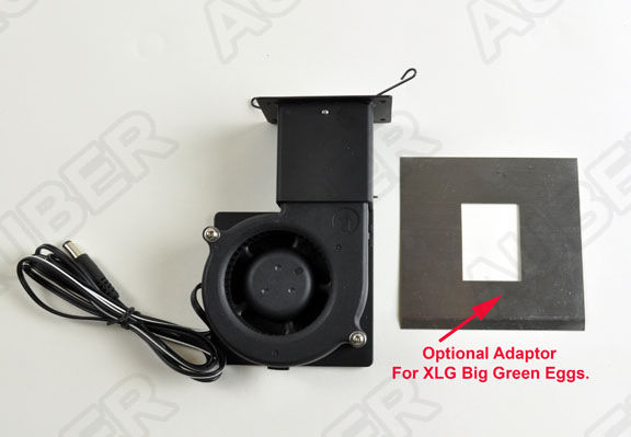
This is the blower fan assembly. This is simply a computer CPU cooling fan I had lying around the house, installed in a plastic hobby box. I have a 1/8" mono headphone jack on the side that is used to connect to the PID controller assembly. Also, it has a 3/4" nipple that will screw directly into the ball valve of my UDS. I need to find a fan grill to cover the fan....

This is the cable I made using 1/8" mono jacks to connect the blower fan assembly to the PID controller assembly output.

Here it is all connected.

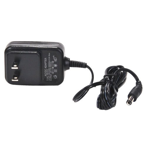
This is the power supply. It is overkill, rated at 4 amps. It is an old laptop power supply I had lying around, it's free, so I used it.
If you want to see a demo video of it in action, go here:
http://www.youtube.com/watch?v=DyK2Ga9TefA&list=UUSvrDenEHxeYFGBls1uyQBQ&feature=share
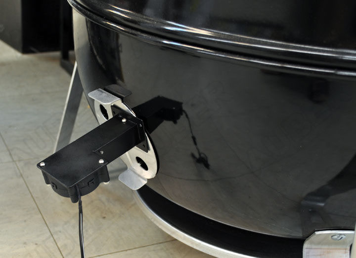
Now I need to mount it to the UDS and give it a try to see if I can get it "dialed in". More to come when I get it going on the UDS.
This is the Auber Instruments Universal 1/32 DIN PID Temperature Controller, 12 VDC. I mounted it in an aluminum housing that I was able to get out of a scrap bin at work.
This is the rear of the housing. You can see the connections here. I originally tried using a banana plug setup for the thermocouple, but found I was getting very inconsistent measurements. I decided to do away with the banana connector and run the thermocouple directly to the PID inside the housing.
Here's the connectors labled to see how where everything is connected.
This is the blower fan assembly. This is simply a computer CPU cooling fan I had lying around the house, installed in a plastic hobby box. I have a 1/8" mono headphone jack on the side that is used to connect to the PID controller assembly. Also, it has a 3/4" nipple that will screw directly into the ball valve of my UDS. I need to find a fan grill to cover the fan....
This is the cable I made using 1/8" mono jacks to connect the blower fan assembly to the PID controller assembly output.
Here it is all connected.
This is the power supply. It is overkill, rated at 4 amps. It is an old laptop power supply I had lying around, it's free, so I used it.
If you want to see a demo video of it in action, go here:
http://www.youtube.com/watch?v=DyK2Ga9TefA&list=UUSvrDenEHxeYFGBls1uyQBQ&feature=share
Now I need to mount it to the UDS and give it a try to see if I can get it "dialed in". More to come when I get it going on the UDS.