• working on DNS.. links may break temporarily.

DIY PID Controller

B

Billie

Guest
Hi everybody,
Smoke in NJ asked me how i built my PID controller and instead of replying in PM i thought I'd share it with all you guys ;)

It all started when i made my third PP...I got tired with staying all night long by my Q, just to keep sure it stayed at a stable temperature...
I looked everywhere for a system, but all of them were more expensive than i could afford...

So i started with a budget of 50€ (about 66$) and went out on the Internet and found the most expensive parts i needed...
I bought two fans which cost about 5$ for the two of them...
2011-07-26161457.jpg


The PID controller was about 10$...you can find them cheaper if you shop around. I bought the 12/24V one --> D1S-2R-24, but a better choice would have been the D1S-VR-24 because of the SSR relay.
%21BuydbgwBmk%7E$%28KGrHqMOKkUEvO9Tt5yuBMBwqIOiS%21%7E%7E_12.JPG


The other small parts (switches, connectors, jacks, box, ...) i bought in a local electronics store...
All together i went 6$ above my initial budget...

Here is the schematic for connecting all the parts...
PID-Schemaaangepast.jpg


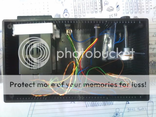
And for those of you that like Pr0n...
The internal parts...
DSC_0139.jpg


The outside of the box...
DSC_0138.jpg


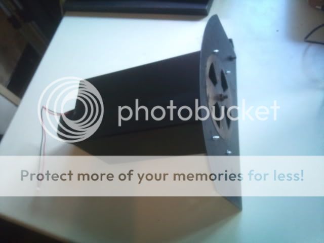
Here i mounted the fan to the door of the Q...
2011-07-27184321.jpg

2011-07-27184304.jpg


For those of you that would like to see the PID in action...
MOV_0143.mp4 video by BillieChillie - Photobucket@@AMEPARAM@@http://vid893.photobucket.com/player.swf?file=http://vid893.photobucket.com/albums/ac134/BillieChillie/MOV_0143.mp4@@AMEPARAM@@vid893@@AMEPARAM@@893@@AMEPARAM@@ac134/BillieChillie/MOV_0143@@AMEPARAM@@mp4 and MOV_0144.mp4 video by BillieChillie - Photobucket@@AMEPARAM@@http://vid893.photobucket.com/player.swf?file=http://vid893.photobucket.com/albums/ac134/BillieChillie/MOV_0144.mp4@@AMEPARAM@@vid893@@AMEPARAM@@893@@AMEPARAM@@ac134/BillieChillie/MOV_0144@@AMEPARAM@@mp4 the PID is in Autolearn mode.

Hope you enjoyed this read ;)

Greetings Tom
 
Hi everybody,
Smoke in NJ asked me how i built my PID controller and instead of replying in PM i thought I'd share it with all you guys ;)


Here is the schematic for connecting all the parts...
PID-Schemaaangepast.jpg


Greetings Tom

Whats the value of the resistor between points A and B? and what wattage (1/2 or 1)?
 
Thanks so much. This is something I want to try; once I get up the courage.

The pid controller costs less than what I've seen around. More googling for me.
 
I applaud homebrewing a controller. I made my own a couple of years ago and have been tweaking at it ever since.

My problem with using a controller such as you've decided on is that the fan is either 100% on or 100% off. When the fan is fully on it will blow a huge amount of air into the cooker until it reaches the target temperature. The problem is that after the fan turns off the temperature will continue to climb. The temperature swings will be very wide. I found that turning the fan on by varying degrees worked best.

There's a huge discussion going on over on the Virtual Weber Bullet board about this very thing. Some of those guys have gone WAY overboard with all sorts of software stuff that this hardware engineer doesn't understand.

http://tvwbb.com/eve/forums/a/tpc/f/9270072103/m/909108292

Russ
 
Wow! It's like your talking French. I did understand any of it, but I looks great. Good job.

Thanks. It actually Dutch. :)

Whats the value of the resistor between points A and B? and what wattage (1/2 or 1)?

That's a K-Type Thermocouple

My problem with using a controller such as you've decided on is that the fan is either 100% on or 100% off. When the fan is fully on it will blow a huge amount of air into the cooker until it reaches the target temperature. The problem is that after the fan turns off the temperature will continue to climb. The temperature swings will be very wide. I found that turning the fan on by varying degrees worked best.

Hey Russ,

First of all thanks for the nice comment :)

Actually that's what a PID does...It calculates the time it takes to get to a certain temperature. The first time it will overshoot, the next time a little bit less and the third time it will stay at the set temperature. When the PID notices that the temperature is dropping it will activate for a few seconds. If you like the theory behind a PID see the wiki. ;)
I got mine tweaked (autolearn modus of the unit) to 0.2°C (0.36°F correct me if i'm wrong) offset... Which means that if i set my temperature to 230°F (110°C) it doesn't go above 230.36°F (110,2°C) and below 229.64°F (109,8°C)

Which is just fine by me ;)

Oh and in the schematic there's a potentiometer in the circuit of the fan. So i could change the speed of the fan if necessary. The only thing is i think 100ohm isn't enough, because that one burned out on the first try. So mine is built with the potentiometer, but it isn't connected any more...


Greetings
 
You have 2 options

I applaud homebrewing a controller. I made my own a couple of years ago and have been tweaking at it ever since.

My problem with using a controller such as you've decided on is that the fan is either 100% on or 100% off. When the fan is fully on it will blow a huge amount of air into the cooker until it reaches the target temperature. The problem is that after the fan turns off the temperature will continue to climb. The temperature swings will be very wide. I found that turning the fan on by varying degrees worked best.

There's a huge discussion going on over on the Virtual Weber Bullet board about this very thing. Some of those guys have gone WAY overboard with all sorts of software stuff that this hardware engineer doesn't understand.

http://tvwbb.com/eve/forums/a/tpc/f/9270072103/m/909108292

Russ

1.You can just add an adjustable resistant on fan, and tune the speed much lower.

2.You need a better thermostat with PID output. variable voltage output is even better than SSR output.
 
1.You can just add an adjustable resistant on fan, and tune the speed much lower.

2.You need a better thermostat with PID output. variable voltage output is even better than SSR output.


Nice you didn't have to say anything as what he is doing could take business away from you but instead like a true bretheren you lended your advice.. Nice job and in the sprit of the bretheren...:thumb:
 
Very cool Billie. I am about as dumb as you can be when it comes to electronics, however my FIL can talk to another country with a tin can, 2' of rope and a coat hanger. :shocked:
Luckily for me, he has siad that he would help me build 1 or 3 of these. Would it be possible for you to list the parts, including the misc. and whatnots. He is in Arkansas right now but coming home in a few weeks and I would love to have all the parts when he got here so I can put him stright to work. Just like he always does to me:becky:
 
Perhaps a day late and a dollar short, but I have questions about this design.

I have found the Sestos D1S-VR-24 on eBay, and I am wondering if you can connect the 12V directly to the 12V SSR output or will that blow the controller?

I've seen other PIDs with SSR control that require a separate SSR.

Thanks
 
If the PID has a built in SSR, you will have to run the 12vdc fan power through the SSR output relay contacts. If, however, your PID has SSR control you will have to use a separate SSR. The controller I built has SSR control, so I had to use an external SSR. My build thread is here. I have a diagram in pdf format somewhere. I'll try to find it after work.
 
^^^What Lightning said^^^. An SSR is a Solid State Relay. The difference between an SSR and standard relay is the way the contact closure is made. In a standard relay, and electrical current is passed through a magnetic coil, which then retracts a solenoid, which closes a set of mechanical contacts; much like flipping a light switch, but electrically. A solid state relay uses transistors (way over-simplified, but suitable for explanation) which activate to allow current to flow when triggered. The advantages of the SSR over a standard relay are the response time and lack of moving parts.
 
If the PID has a built in SSR, you will have to run the 12vdc fan power through the SSR output relay contacts. If, however, your PID has SSR control you will have to use a separate SSR. The controller I built has SSR control, so I had to use an external SSR. My build thread is here. I have a diagram in pdf format somewhere. I'll try to find it after work.

I believe the PID does have the SSR built in with a 12VDC output, I cannot find any info on the max load it can carry. The fan will draw an amp or less.
 
Wow, looks really simple to put together. A parts list would be great since you have already done the hard part :thumb:
 
Back
Top