Making my own Stoker...(Heatermeter) plus Router mod

Theboz1419

is one Smokin' Farker
Joined
Aug 13, 2009
Messages
554
Reaction score
187
Points
0
Location
Puyallup...
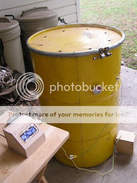
I have been following a thread over at the Virtual Weber for making a bbq Blower thats can be controlled over the internet, using a old linksys router and homemade circuit boards.

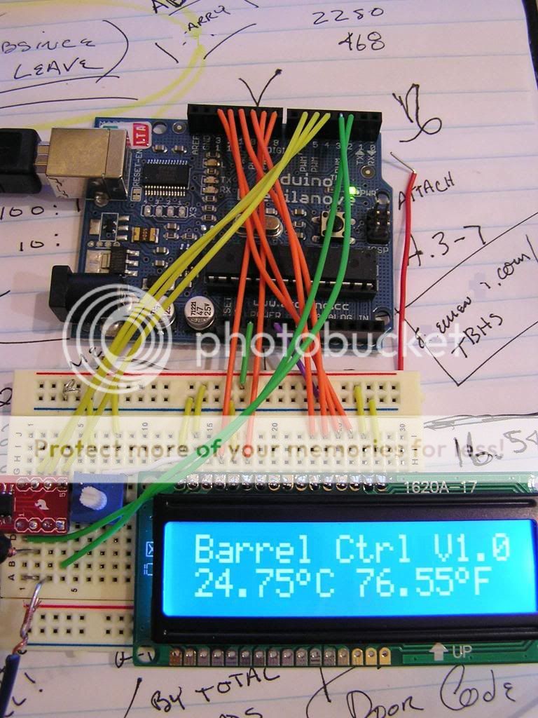
Its not much yet but I have started my own heatermeter and so far its going well with a few minor bugs here and there.

Im also learning as I go. I have soldered in the past but nothing to talk about and i never programmed before, so this will be my summer project.

http://tvwbb.com/eve/forums/a/tpc/f/9270072103/m/7691098906

Some pics of what i have so far and will update as I go. I am still waiting for all the parts to be able to start on the main circuit board and button board. I already have the router programmed( i believe, lol)

20582120172233552741384.jpg


The above pic is a SD card reader that i took apart and then I installed it to the router, after a few different card readers and soldering hicups, it works really good and now has 2 gigs of storage for files needed for the meter and i can save graphs of temps throughout a smoke.

20793520217900294381384.jpg


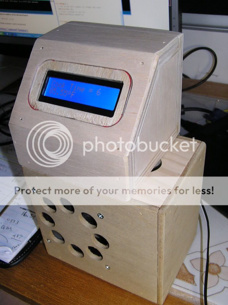
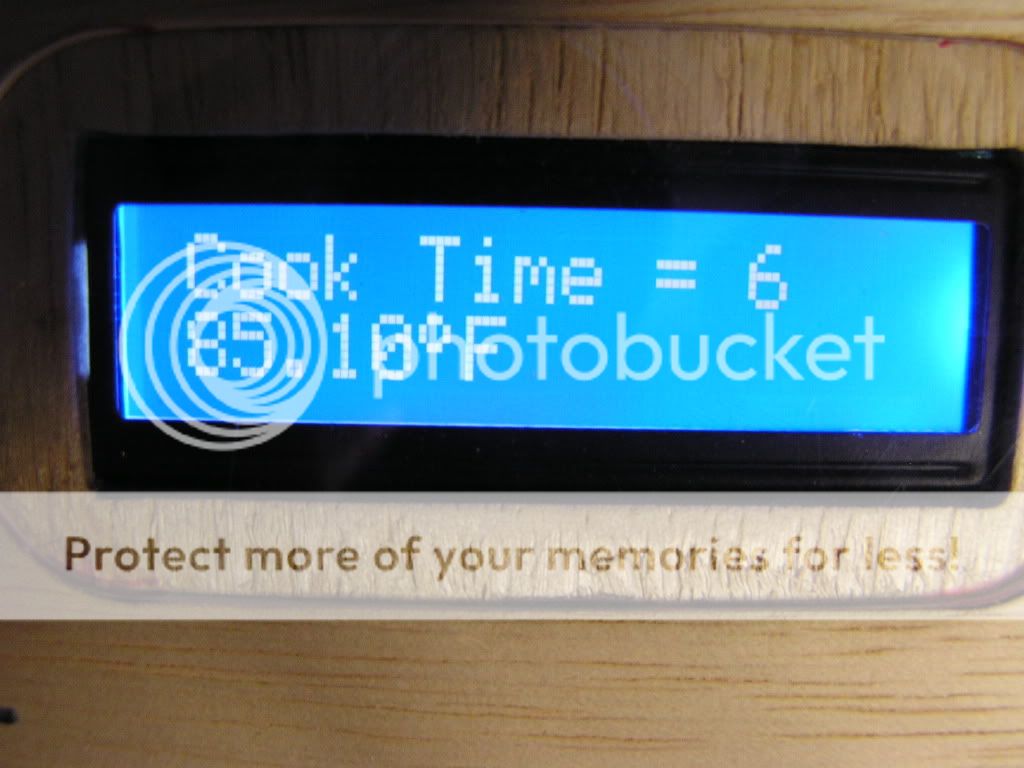
This will be the heatermeter, it will have all needed connections on the back end and on top you can see a LCD screen and some future buttons.


Hopefully, I'll have it either finished and working or it will be up in smoke lol, before the end of the summer.
 
I thought I was the only weirdo doing this! Just finished mine
yesterday.
I went with an Arduino micro controller.
I also used a MAX6675 thermocouple amplifier and
k-type thermo couple.
Here's a picture of it bread boarded together
Thermo1.jpg

Here's a picture of it in the small box I built to house it
P4200021.jpg

Here's a picture of the display
P4200023.jpg

Here's a picture of the whole setup with UDS
P1010026.jpg

And here's the pork I just pulled off of it a little while ago (It's in the cooler now as we speak)
P1010027.jpg

While it did work... I have some programming to do yet. So far, it's just
on/off at 225. But it needs a stepping program to avoid over running etc.
I'm also not sure about my blower setup yet. I'm thinking it may need
a pipe or something to focus the air into my basket vrs just blowing
straight into the drum. Only time will tell. :-D
 
That is a ridiculously cool project. I wanted to try something like that but went the cheap/lazy route and made a PID controller. I'll be subscribing to watch your build for sure!
 
Buttons arrived today

I recieved my buttons and the microcontroller(ATMega328), the brain, basically.

It ain't very pretty but 30 minutes of work and my first ever button board I can't complain, lol. It works great, each buttons gets a different ohm reading(2.2, 4.7, 390, 680) to let the ATMega know how to move the cursor on the LCD up, down, left, right.

buttonsr.png


20745520309852593131384.jpg


I am definately going to redo the board to make it nice, in the future, but for now it works fine.
 
heatmeter.png


After banging my head on the wall for the last few days, I was finally was able to get a Web page of the Heatermeter up and running. Nothing to show as of yet, still need some parts. But i hope to start on it this week and should be finished by the end of next week.
 
you guys ain't the only ones on that thread!

I've build the ultra simple version. Arduino, one pit sensor, fan mounts up to my BGE. using Bryans code.

After working out some kinks with my soldering this weekends cook was rock solid. I did a brisket and rocked 190* for the first two hours followed by 240* to the finish line.

I had a Maverick monitoring the pit temps the whole time and even with a small window the alarms never went off. I only had to touch it to change the pit temp from 190*->240*... other than that, I put the brisket on and came back when it was almost done!
 
Yeah, Byran and Ed have done alot of cool stuff. I was thinking about getting a stoker or a guru, but after seeing what they have done i wanted to make my own, hell, I made my UDS I might as well make my blower for it.

I never built any thing even close to this so thats why i started a thread over here, showing that even a newb with no programming and who has never made a circuit board can do this abeit with some minor hiccups here and there.
 
Started some work on the main board, still waiting for components to finish.

From left to right: 2-22pf caps, 16mhz crystal, a header for the AtMega 328, Header for the shift register, and the header for the LCD screen
22160620497185276331384.jpg


The underside is going to be a jungle of wires.

22405220497195276581384.jpg
 
other than saving a little coin and giving yourself a whole lot more work, is there an advantage I'm missing to using the shift register VS an already serial enabled LCD

:confused:
 
That stuff is so cool... Is it hard to do for non-geeks???
 
other than saving a little coin and giving yourself a whole lot more work, is there an advantage I'm missing to using the shift register VS an already serial enabled LCD

:confused:


For that I have no clue, I have never did anything like this. The one reason i can come up with is that the serial enabled cost twice as much as the parallel lcd including the shift register and from doing my little search on them the one from sparkfun has some glitches.
 
That stuff is so cool... Is it hard to do for non-geeks???

The hardest part is learning how to read the schematics, What connects to what? and what is some of the terms, like vcc, icsp, ohm, ect....,

Then there is the soldering, and that just takes practice practice and some more practice.

My problem so far is the placement of the components of the circuit board. not knowing whats the best to get everything as small as posible.

But i look at as if i need a bigger box to put it in so be it as long as it works it fine by me.
 
The arduino route was real easy really, I had allot of trouble wrenching the thermocouple amp. Smartfun had the parts though. Adafruit has an amp board already put together so it would be even easier to use. It's not that hard if you have basic electronics tinker' skills and basic C programming.
 
So I'm not the only one, eh???

Mind you I have no farkin CLUE how to do any of that chit.....BUT I have a friend who's an electrical engineer who does!!!:becky:

He's already ordered all the parts and is only waiting on a couple more before he starts putting it together for me. Paying him in BBQ (HIS idea)!!:thumb:
 
It is so doable by more people than you know. I would ask if these silicon artists could lay some schematics on a brother.......
 
I think these things are cool but what do you have as far as total $$ and time involved in getting your projects finished? What do you gain over what is on the market other than personal pride that you made your own?

Its really interesting and soldering boards and stuff is kinda fun for me but the programming is the bain of my existence! lol. Sure I do some web programming for my website but most of that is cut and paste and modifying to do what I want it to do.

I would be interested in doing something like this as I have plenty of old routers and wireless gear around here as well as some Maverick wireless thermo's which could be sacrificed but I'm scared of ruining the thermo's (I still use'em)
 
For that I have no clue, I have never did anything like this. The one reason i can come up with is that the serial enabled cost twice as much as the parallel lcd including the shift register and from doing my little search on them the one from sparkfun has some glitches.

well i'm finishing up a none web enabled 4 probe 2 pit unit at this time so i went straight 4bit parallel b/c i didn't need the extra I/O, but i've got one of these from adafruit to play with also:

i2cspilcdbackpack_MED.jpg

for $10 i'll take lazy :becky:

i'm currently just using the full-on UNO board w/headers and may switch to backpack or headerless style, but i'm not going to go full out discrete like you. back in the day i would've been all over it but nowadays i'm still just lazy.

kudo's for going the harder route and learning stuff :thumb:

if you're using mav style probes do you have a source for the ridiculously tiny mini-jacks?

thx for the pics and updates, keep it coming.
 
Ok, I have been having some problems with the build. I have builded the circuit board twice using wire connects(over 90 plus wires of 30awg) and I could not get the thing to do anything, except I was able to program the Atmega328 chip without problem on the circuit board.

I figured it was something I was doing wrong wiring up the LCD screen connections. Then, after emailing I found out I was not programming it correctly.

But, After a week of frustration and never wanting to wire up a 3rd board with tons of wires any time soon. I decided to give homemade PCBs a try, and for my first ever, think i could not be more happier with the results.

Now, I have to drill out the connections and i will have just about 25 wires still to wire after.

I will get this thing working one wa or the another, lol.


firstmd.jpg
 
Back
Top